Overview
This document details the interface to the Link Labs LTE-M Module. This interface consists of a point-to-point serial communications protocol, intended to be used over a UART and GPIO connection to the Link Labs LTE-M modules. This connection is referred to as the “Host Interface”. A simplified block diagram is shown below.
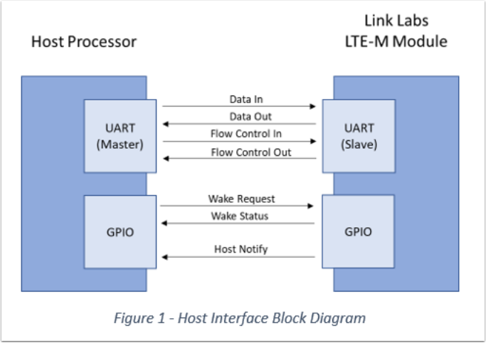
The UART connection utilizes a Master/Slave protocol, with the Link Labs LTE-M module always running in slave mode. The protocol allows for data exchanges to be initiated by both master and slave devices, although the initiation mechanism is different.
Communication Transactions
The host processor (UART Master) can initiate a new communications transaction at any time by sending a command packet over the UART. All communications are initiated by the master by sending 1 command packet, and waiting for a full response packet before sending another command packet. The slave responds immediately to 1 command packet with 1 response packet. The slave is guaranteed to respond with TH1 seconds. Unsolicited responses from the slave device are not allowed.
The Link Labs Module Processor (UART Slave) cannot initiate a UART transaction by sending data bytes directly. Instead, the slave processor initiates the transaction by asserting the Host Notify GPIO line. The expectation from that point forward, is that the master should immediately respond to the level change on the Host Notify line by sending a UART command to query the reason for the notification, through a command called the “Host Interface Interrupt Flags”. Based on the response to that command, the master should determine what additional actions and communication is necessary.
The Host Notify line is asserted when an interrupt flag is set in the LTE-M module, and is de-asserted when all notification flags are cleared. The host processor is responsible for clearing the interrupt flags through a UART command, which returns the Host Notify line back to the de-asserted state.
Interface Signaling
The Link Labs LTE-M module is a highly optimized for extremely low-power operation, in order to achieve a very long battery life on small form factor batteries. In order to meet these design goals, the LTE-M modules typically goes to a low-power sleep mode automatically when it deems appropriate. The host processor is required to wake up the LTE-M module (and wait for confirmation that it is awake), while UART transactions occur. A diagram of the required signal waveforms is shown below, and the sequence is described as follows:
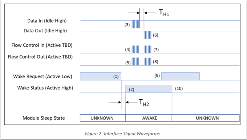
When the host is ready to initiate a UART transaction, it does not know whether the LTE-M module is in the sleep or awake state. The host initiates the transaction by asserting the Wake Request line (1). Within TH2 seconds, the module will assert the Wake Status line (2). From that point forward, the host can safely assume that the module is awake. The module will remain awake for as long as the Wake Request line remains asserted.
Once the Wake Status has been asserted, the host can safely send a UART command (3) using byte-level flow control (4,5). Once the entire UART command is sent, the module is guaranteed to respond within TH1 seconds (6), also using byte-level flow control (7,8). Once the UART response is complete, the host can keep the module awake and send more UART commands, indefinitely.
Once the host is finished sending UART commands and receiving UART responses, it should allow the module to go back to sleep (if low power operation if desired). This is communicated by de-asserting the Wake Request line (9). At some point after this, the module will de-assert the Wake Status line (10). Once the Wake Status line is de-asserted, the host does not know whether the module is awake or asleep. This marks the end of the transaction.
Sequence Diagrams
The following sections detail notional diagrams of the sequences involved in sending data from the LTE-M Module up to the Link Labs Cloud Server (“uplink”), and from the Cloud Server down to the LTE-M Module (“downlink”). Please refer to the Command and Response specifications in the following section for exact details and parameters.
Note that the Cloud Server is accessible from any internet enabled device with the proper access credentials, effectively creating a secure wireless Internet-Of-Things network with any LTE-M Module that is in an LTE-M coverage area.
Uplink Transmission
The following sequence diagram illustrates the events involved in the successful uplink of a packet from the host processor through the LTE-M Module to the Link Labs Cloud Server
The sequence begins by the host sending the uplink payload over the UART in the UPLINK_SEND command. Immediately after that, the LTE-M module will respond with an ACK code (typically indicating success) as well as a Packet ID that is to be associated with this uplink attempt instance in the events that follow. As is shown in the diagram, a success code received at this point only indicates a successful queueing of the uplink payload, not a successful delivery to the cloud destination. If an error is returned, then the uplink payload was not able to be queued and the uplink attempt is terminated. The host should at that point determine if it should try again immediately or wait until a later time.
If the UPLINK_SEND command returns a success code, the LTE-M Module will then attempt to push the message up to the cloud server. In a properly configured device this will typically be successful, unless the device is out of the coverage area of the LTE-M network. All further events in this sequence are optional and purely for information purposes or for system optimization purposes (e.g.- the Notify GPIO allows a host processor to enter a low power Wake From Interrupt state).
Regardless of the uplink attempt result, the LTE-M Module will always generate a status report on the uplink attempt. First, the Host Notify flag is set. The expected action from the host at that point is to send the INTERRUPT FLAGS command. The response to that command will be “TX_DONE” if the uplink attempt is finished, or some other flag if a different event has occurred.
If the “TX_DONE” flag is set, the host is expected to send the UPLINK_STATUS command, to find out the result of the uplink attempt. This command will return an ACK Code (success, or an error code indicating the reason for failure), a Packet ID (specifying exactly which uplink attempt instance is being reported on this will match the Packet ID returned in the UPLINK_SEND command) and a Transit Time (how long the uplink sequence took from the reception of the initial UPLINK_SEND command until a confirmation from the Cloud server was received).
Downlink (Always On)
TBD
Downlink (eDRX)
TBD
Downlink (Mailbox Mode)
The LTE-M module contains a downlink mode referred to as “Mailbox” mode. In this mode, any internet enabled device can send a message to an LTE-M Module, through the Cloud server. The message is cached in the Cloud server, and remains there until the LTE-M Module is commanded locally to “check its mailbox”. This command triggers the LTE-M module to query the Cloud Server, for the presence of a cached message.
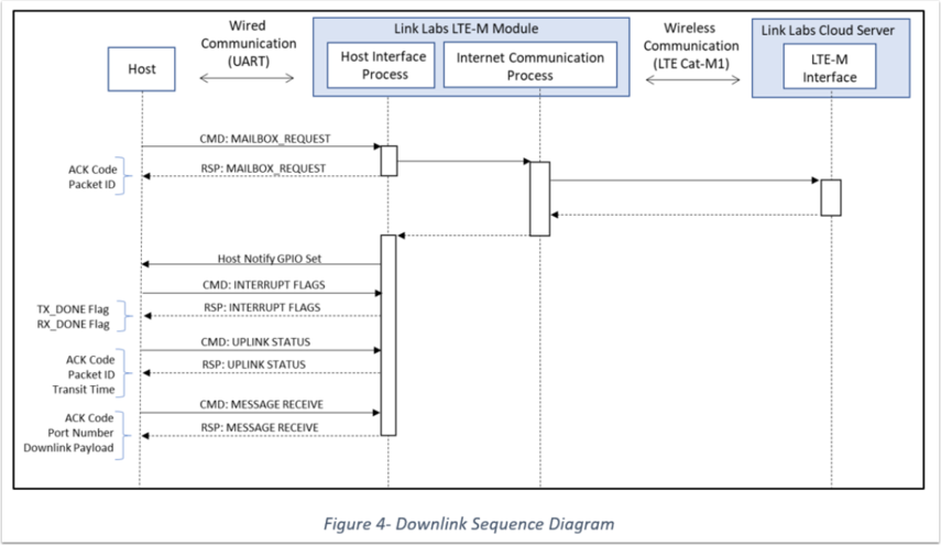
The mailbox mode sequence is very similar to the Uplink sequence. The Mailbox Request is treated as an uplink message, although there is no uplink payload to deliver. Hence, the Mailbox Request update is given a Packet ID and an uplink status report, identically to that of an uplink message. Additionally, if a downlink message is present in the Cloud Server, the “RX_DONE” Interrupt Flag will be set as shown in Figure 4. If the RX_DONE flag is set, the host is expected to send the MESSAGE_RECEIVE command, in order to extract the downlink message.
Command/Response Format
All UART commands must conform to this general format:
| UART Master Commands: | ||
|---|---|---|
| Byte Number | Description | Comments |
| 0 | Start of Frame | Always equal to 0xC5 |
| 1 | Command Byte | Specifies which master command is contained in this message. |
| 2 | Command Version | An 8-bit number used to indicate the version number of the command. |
| 3 | Message Number | An 8-bit number incremented by the master device. Expected to rollover: 253, 254, 255, 0, 1, 2, ... |
| 4 | Payload Length (MSB) | Most significant byte of the payload length. Note that the maximum payload length is 256 bytes. |
| 5 | Payload Length (LSB) | Least significant byte of the payload length. |
| Payload Byte 0 | ||
| Payload Byte 1 | ||
| Payload Byte 2 | ||
| ... | ... | |
| Payload Length + 6 | Checksum Byte (MSB) | The MSB of a 16-bit CRC. See the "Checksum" section for details. |
| Payload Length + 7 | Checksum Byte (LSB) | The LSB of a 16-bit CRC. |
| UART Slave Responses: | ||
|---|---|---|
| Byte Number | Description | Comments |
| 0 | Start of Frame | Always equal to 0xC5 |
| 1 | Command Byte | Specifies which master command is being replied to. |
| 2 | Message Number | Specifies the message number that is being replied to. |
| 3 | ACK Byte | See "Acknowledgement Byte" section. |
| 4 | Payload Length (MSB) | MSBof the total number of bytes in the payload. |
| 5 | Payload Length (LSB) | LSBof the total number of bytes in the payload. |
| Payload Byte 0 | ||
| Payload Byte 1 | ||
| Payload Byte 2 | ||
| ... | ... | |
| Payload Length + 6 | Checksum Byte (MSB) | TheMSB of a 16-bit CRC. See the “Checksum” section for details. |
| Payload Length + 7 | Checksum Byte (LSB) | The LSB of a 16-bit CRC. |
Release Notes
v0.5.4
20180523
Tested with bootloader v1.6, Sequans v5.1.1.0-36417
New Features (from v0.5.1):
- Power - Monarch boot and attach time are reduced in On/Off mode, resulting in lower energy usage per Tx/Rx event.
- FOTA - FOTA download rates have increased from 2kbps to ~10kbps.
- Messaging - Uplink stream burst data rates have increased from 9kbps to 18kbps.
Known Issues:
- PSM mode (Beta) cannot be used on an LL2E20 board if the CTS rework is not applied.
- In PSM mode (Beta), sometimes the signal strength fields do not get populated, this can lead to an increase in power consumption or even a software reboot.
- In PSM mode (Beta), the behavior of the module in response to a reset command is different than in On/Off mode.
- During a FOTA download, sometimes the download stops midway. If this happens, the firmware cancels the download and continues operating normally. This happens roughly 20% of the time, so a second attempt is sometimes required to perform a FOTA upgrade.
v0.5.1
20180326
Tested with bootloader v1.6, Sequans v5.1.1.0-34234
New Features (from v0.3.7):
- Extend user uplink max length from 256 to 1280, raising max uplink throughput to ~10kbps.
- Fix high sleep current during Monarch OFF on LL2E30 boards.
- Fix UART interface issue that was preventing communication with a Raspberry Pi host.
- Added command to get detailed status report with Cell ID/ Location Area Code / RSRP / RSRQ on a per-packet basis.
- Add a two-stage reset command to give host more options for shutdowns.
- Added network info request command and read command. Network info includes local and UTC time, cell id, tracking area code, RSRP, RSRQ.
- Added packet retransmissions for improved robustness.
Known Issues:
- In PSM mode (Beta), sometimes the signal strength fields do not get populated.
- In PSM mode (Beta), sometimes transmissions do not arrive reliably.
- During a FOTA download, sometimes the Sequans chip crashes. The download fails and the module reboots to recover.
v0.3.7
20180126
Tested with bootloader v1.6, Sequans v5.1.1.0-34234
New Features (from v0.2.3):
- Fixed state of CTS line that was causing high sleep current on some hardware installations.
- Adds PSM mode in Beta testing stage.
- Reduced transmission overhead and latency.
- User messages max size changed (Uplink/Downlink) FROM: 256/128 TO: 256/256
- Added registration check at boot, which ensures registration integrity.
- Increased registration timeout to 1 minute.
- Fixed state machine issue that was causing loss of state sync during some LTE chip shutdowns.
Known Issues:
- In PSM mode (Beta), sometimes the signal strength fields do not get populated.
- In PSM mode (Beta), sometimes transmissions do not arrive reliably.
- During a FOTA download, sometimes the Sequans chip crashes. The download fails and the module reboots to recover.
- If the MCU is configured to periodically check for a new FOTA image, and a FOTA download fails it may not resume periodic checks. A reboot is needed to resolve this condition.