What is the LL-RPT Repeater and what comes in the box?
What is the LL-RPT Symphony Link Repeater?
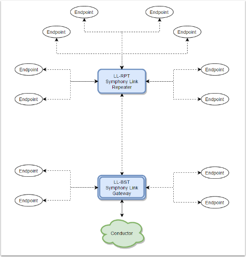
The LL-RPT Symphony Link Repeater is a simple plug in device that can be used to extend the bidirectional communication range of your Symphony Link system. If placed appropriately into a Symphony Link system, the LL-RPT Symphony Link Repeater will act as a store and forward relay. The LL-RPT Symphony Link Repeater will receive data from Symphony Link Modules, and then forward that data to your Symphony Link Gateway, where it will finally be forwarded to the Conductor data management platform. The LL-RPT Symphony Link Repeater will also forward data received from your Symphony Link Gateway to the appropriate Symphony Link Module.
Key Features
- Greatly extends the range of a Symphony Link system
- Simple and fast system synchronization
- Just needs power!
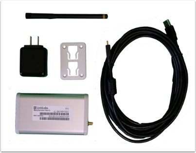
Your Symphony Link Repeater purchase will include:

1x LL-RPT-915-SYM-I-USB Symphony Link Repeater
1x Mini-USB to USB-A cable
1x 120 VAC to USB wall plug
1x 900 MHz Symphony Link antenna
1x Mounting bracket
Minimum system requirements
Repeater functionality was introduced in the 1.5 release of Symphony Link. This means the other components of the Symphony Link network must be operating with the following minimum software requirements:
- LL-BST-8 gateway software version 1.5.2 or later
AND
- LL-RLP-20 and LL-RXR-27 module firmware version 1.5.0 or later
How do I configure a repeater for a Symphony Link network?
You can automatically configure your LL-RPT repeater to operate on a particular Symphony Link network by attaching the repeater to one of the network's gateways. This section explains how.
Step 1: Remove power from the LL-BST-8 gateway by unplugging its power adapter.
Step 2: Connect the repeater's mini-USB port to either of the gateway's USB ports using a mini-USB-to-USB patch cord.
Step 3: Supply power to the LL-BST-8 gateway by plugging-in its power adapter.
Step 4: Wait for about 1 minute while the repeater synchronizes its network configuration to the gateway.*
Step 5: Again, remove power from the LL-BST-8 gateway.
Step 6: Detach the repeater from the gateway by removing the USB patch cord.
Step 7: Again, supply power to the LL-BST-8 gateway.
Step 8: Supply power to the LL-RPT repeater by plugging it into a typical wall receptacle using the USB-to-wall-plug adapter.
*At the end of the system synchronization, the gateway resets the repeater. If you leave the repeater attached to the gateway via USB, the gateway will continuously synchronize with and then reset the repeater.
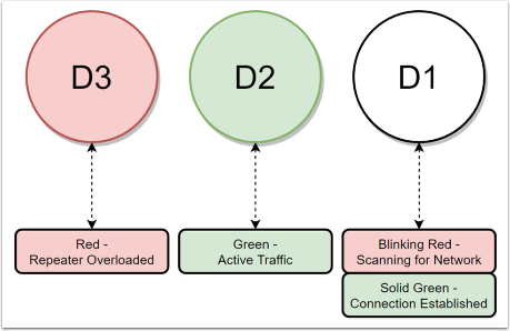
What do the LEDs mean?

How do I test the repeater using a network tester?
This article describes how to test the coverage of a repeater using a network tester.
Required equipment
1 LL-BST-8 Symphony Link gateway (with minimum software version 1.5.2)
1 LL-RPT Symphony Link repeater
1 LL-NT Symphony Link Network Tester
- The LL-RXR-27 module on the network tester must have Symphony LInk firmware version 1.5.0 or later.
- The EFM32 host microcontroller on the network tester must have Network Tester firmware version 1.0 or later.
Procedure
Configure the Network Tester to use the desired Network Token. (A Gateway, a Repeater and a Network Tester can only talk to each other if they advertize the same Network Token.)
- Turn on the Network Tester.
- Navigate to the "Set Network Token" menu option using the middle button. Then select the "Set Network Token" menu using the right button.
- Set the desired Network Token:
- Tap the right button to change the digit under the cursor.
- Hold the right button to move to the next digit.
- Toggle down to "apply" using the middle button. Then press and hold the right button to apply the changed Network Token.
- Exit to the Main Menu using the left button.
Once the Network Token is properly configured, the Network Tester will automatically connect to the Gateway. To force the Network Tester to connect through the Repeater, do the following:
- Follow all the steps of this article to connect the Repeater to the Symphony Link network.
- Wait for the Repeater's D1 LED to turn solid green. This indicates it is connected to the network.
- On the Network Tester, navigate to the "Connection Filter" menu using the middle button. Then select the "Connection Filter" menu using the right button.
- Select the "Repeaters Only" option.
- You should see a smiley-face-looking icon to the right of the selected option.
- Use the left button to return to the Main Menu.
- Navigate to the "Network Diagnostics" menu.
When connected to the Repeater, the D1 LED on the Network Tester should go solid red, the "Network Diagnostics" should display the last 8 digits of your Symphony Link Gateway's ID, as well as an RSSI read-out that shows the current signal strength received from the Repeaters beacon.
Example Network Topology Diagram

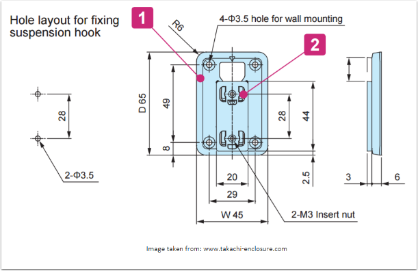
Mounting Diagram

Theory of Operation
This is how things work
Without repeaters, the Symphony Link network is a pure star topology. Inserting a repeater introductes a "single hop" into the topology. That is to say, a Symphony Link module can communicate with a Symphony Link gateway through at most one Symphony Link repeater.
The concept is pretty simple. To a gateway, a repeater looks like an end-node module. To an end-node module, the repeater looks like a gateway.
All normal functionality of the Symphony Link system is preserved when repeaters are introduced to the network.
Maximum Number of Repeaters on a Symphony Link Network
We strongly recommend against using more than two repeaters per Symphony Link Gateway. While the theoretical limit is much higher than two, due to the high amount on-the-air traffic, we prefer to keep systems limited to two Symphony Link Repeaters per Symphony Link Gateway. For special cases, please contact support@link-labs.com to determine whether a larger number of repeaters is acceptable.
