What is the evaluation board?
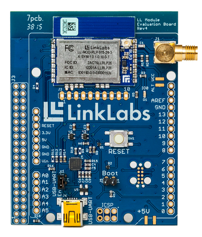
The evaluation board is a carrier board for the LL-RLP-20 or LL-RXR-27 module. The board includes the following features:
- A USB-to-UART bridge (Silicon Labs CP2104) to control the module from a PC over USB
- An SMA connector for convenient routing of the module's RF path
- A Raspberry Pi B+ header to control the module from using a Raspberry Pi
- An Arduino header to control the module using an Arduino
Hardware description and configuration
Powering the evaluation board
There are several options to supply power to the evaluation board's module.
USB
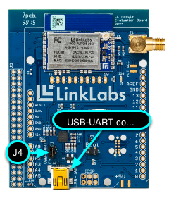
Verify the J4 jumper is installed. Then use a mini-USB cable to connect the USB-UART connector to a USB power supply or PC.
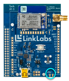
Unregulated external supply
Apply 5 VDC across the gold pads at the bottom edge of the evaluation board. The positive terminal is the left-hand terminal.
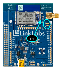
Regulated external supply
Remove resistor R1. Then apply 3.3 VDC across the ALT VCC pads.
Arduino or Raspberry Pi
The module will derive power from a connected Arduino or Raspberry Pi.
Antenna selection
The module on the evaluation board can be configured to transmit/recieve radio-frequency signals via its integrated trace antenna or via an external antenna connected to the board's SMA connector. Use of an external antenna can lead to improved performance relative to the trace antenna. To switch the configuration of the module using the command line utilities provided by Link Labs, please refer to this article.
For operation in the US ISM band (902--928 MHz), Link Labs recommends the Linx Tech ANT-916-CW-HWR-SMA, which is a center-fed half-wave dipole antenna.
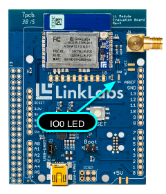
LED indicator
The evaluation board includes a single red light-emitting diode (LED), labeled IO0. The LED illuminates anytime the module sets the host interrupt line (i.e., when one/many of the module's interrupt flags is/are latched).
RESET pushbutton
The evaluation board includes a RESET pushbutton. Depressing this button drives pin 7 low (the module's pin 7). When the button is released, an internal pull-up drives pin 7 high to actuate a hardware reset.
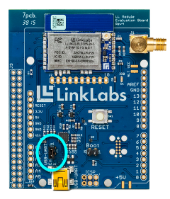
USB-UART jumper
The USB-UART jumper (or J4 jumper) provides a method to disconnect the Silicon Labs CP2104 USB-UART bridge from the module. Disconnecting the bridge may be useful when the USB-UART connection is not needed.
Hardware schematics
Download *pdf files of the evaluation board schematics.LL-RLP-20/LL-RXR-27 evaluation board (Revision 4)
RLP_eval_board_rev4.pdfLL-RLP-20/LL-RXR-27 evaluation board (Revision 5)
RLP_eval_board_rev5.pdfLL-RLP-20/LL-RXR-27 evaluation board (Revision 6 / LL3B60)
RLP_eval_board_rev6.pdfUSB Drivers
To control the evaluation board from a computer, you must first install the drivers for the Silicon Labs CP2104 USB-to-UART bridge. The Windows version of these drivers are packaged with the Prelude Windows installer.
Controlling the module using Prelude
Prelude is a graphical user interface designed to control an LL-RLP-20 or LL-RXR-27 evaluation board from a PC. Download the latest release of Prelude here.
For a quick tutorial on using Prelude to control an evaluation board in Symphony Link mode, please follow the Symphony Link Development Kit Quick Start Guide.
The Prelude User's Guide provides a detailed description of how to use Prelude to control an evaluation board in any mode.
Controlling the module from the command line
Install the drivers for the Silicon Labs CP2104 USB-to-UART bridge
Install drivers for the evaluation board's CP2104 USB-to-UART bridge.
Getting started for Windows
Link Labs provides the following pre-packaged executables for download. These are command-line utilities to control the evaluation board's module over USB.
- symphony_test.exe - a command-line utility to control the module in Symphony Link mode. This allows you to control the module while it participates in a Symphony Link network.
- nomac_test.exe - a command-line utility to control the module in NoMac mode. This utility gives you control of the module's low-level radio parameters.
Alternatively, you can compile any of these applications from the host interface source code using MinGW with MSYS. Follow the MinGW installation instructions for Linux using an MSYS shell.
Attach the evaluation board and identify the serial port
- Connect the evaluation board to your PC using a mini-USB cable.
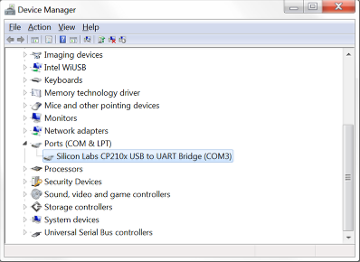
- Open the Windows device manager (using the command window, run devmgmt.msc).
- Serial ports are displayed under Ports (COM & LPT).
- Note which COM port is enumerated by the Silicon Labs CP2104x USB to UART Bridge.
Getting started for OSX and Linux users
For OS X or Linux, create the symphony_test, ensemble_test, lorawan_test or nomac_test binary by compiling from source.
- Download the host interface source code
- Once the download is complete, extract the tar ball to a location of your choice, which we'll refer to as [source_path]
- Open a terminal window
- Change directory: cd [source_path].release_[release]/projects/symphony_test (or nomac_test). Replace [release] with the appropriate release number, e.g., "_1_3_0".
- Make the binary by running make
Once made, the binary (either symphony_test, ensemble_test, lorawan_test or nomac_test) will reside in the exe subdirectory.
Attach the evaluation board and identify the serial port
- Connect the evaluation board to your Mac or Linux machine using a mini-USB cable.
- Open a terminal and run ls /dev/cu* (OSX) or ls /dev/tty* (Linux) to list all serial connections.
- The evaluation board will typically enumerate to a serial port named /dev/cu.SLAB_USBtoUART (OSX) or /dev.tty.SLAB_USBtoUART (Linux). Note the serial port enumerated by the evaluation board.
Changing the default serial port
By default, the "_test" applications talk to the COM3 serial port (Windows) or /dev/cu.SLAB_USBtoUART (OSX) or /dev.tty.SLAB_USBtoUART (Linux). If the evaluation board enumerates to a different serial port, the serial port must be specified with each terminal command.
To address a different serial port, use the -D command as follows:
Windows
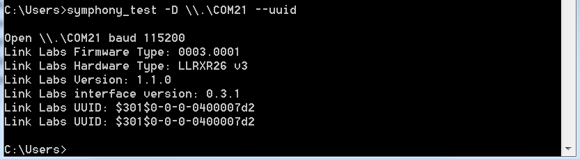
Prefix any command with -D \\.\COMx, where x represents the number of the COM port. For example, to get the UUID of a module connected to COM21 using symphony_test, run the following:
symphony_test -D \\.\COM21 --uuid(Note: lorawan_test does not require the "\\.\" before the COM port.)
OSX
Prefix any command with -D /dev/cu.SLAB_USBtoUARTx, where x represents the number of the COM port. For example, to get the UUID of a module connected to USBtoUART30, run the following:
./symphony_test -D /dev/cu.SLAB_USBtoUART30 --uuid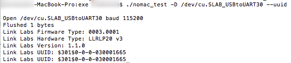
Linux
Prefix any command with -D /dev/tty.SLAB_USBtoUARTx, where x represents the number of the COM port. For example, to get the UUID of a module connected to USBtoUART30, run the following:
./symphony_test -D /dev/cu.SLAB_USBtoUART30 --uuidsymphony_test
This command-line utility is for controlling a module while it participates in a Symphony Link network. To generate a list of available commands, run
symphony_test --help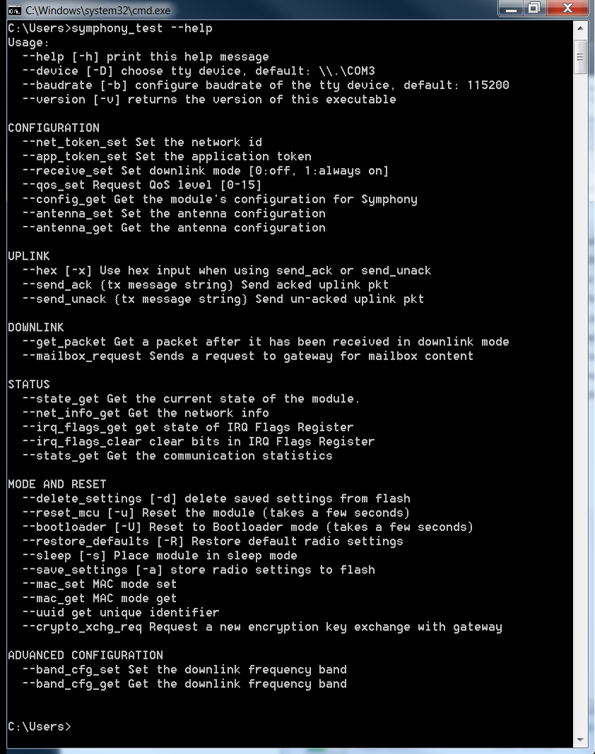
lorawan_test.exe
This command-line utility is for controlling a module using LoRaWAN mode. It exposes all of the LoRaWAN features in the ll_ifc library and turns the PC + module into a LoRaWAN node. The PC can join a LoRaWAN network, send messages and receive messages.
Use the "-D" argument to provide the module's serial port to lorawan_test. If the evaluation board enumerates to COM4, for example, you can query the module's information by sending the "info" command:
lorawan_test.exe -D COM4 info(Remember to replace COM4 with your actual serial port.) The output should look like:
I 00000000 src/main.c:992: ll_tty_open(COM4, 115200)
Open COM4 baud 115200
I 00000000 src/main.c:1000: Command "info" with 0 arguments
Link Labs Firmware Type: 0003.0001
Link Labs Hardware Type: LLRLP20 v3
Link Labs EUI-64: a0bb3e0030001419
Link Labs UUID: $301$0-0-0-a0bb3e0030001419
You can display the application's help file by sending the "help" command:
lorawan_test.exe helpnomac_test.exe
This command-line utility is for controlling a module using NoMac mode. To generate a list of available commands, run
nomac_test --help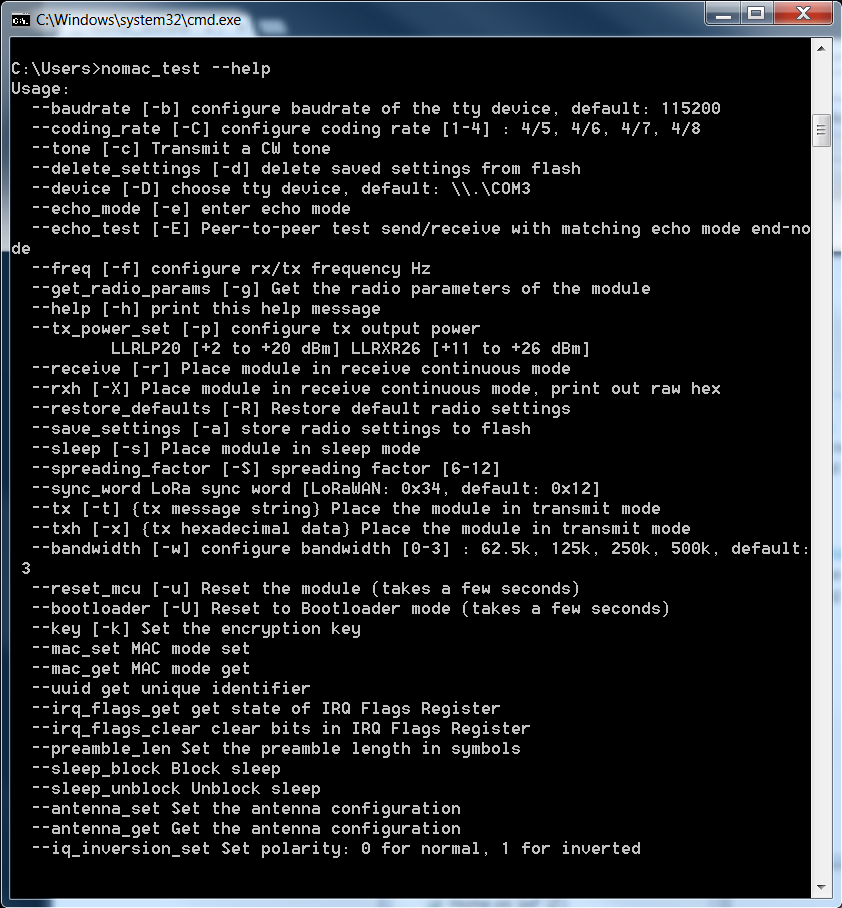
Connecting the evaluation board to Arduino Due
This article is for the Arduino lovers in the crowd. It describes hardware configuration to control an LL-RLP-20 or LL-RXR-27 evaluation board using an Arduino DUE.
Once you get the hardware setup, please refer to this article to start your software development.
Why use Arduino Due?
The LL-RLP-20 or LL-RXR-27 module is designed to be controlled over UART. This means the Arduino must dedicate a serial interface to control the Symphony Link module.
Unfortunately, the most common Arduino boards (like the UNO) have only one serial interface (digital pins 0 and 1). This interface is used by the Arduino to communicate with a PC and it is the interface typically used to write firmware to the Arduino from the Arduino IDE. This makes it difficult to control a Symphony Link module without substantial modifications to the Arduino platform.
The Arduino Due, on the other hand, possesses several serial interfaces, and therefore it can easily be used to control a Symphony Link module without the need to modify Arduino's default use of pins 0 and 1 for programming, monitoring, etc.
Setting up the Due
You might need to install drivers for the Due. Arduino has tons of great documentation to get started with the Due and the Arduino IDE.
Wiring diagrams
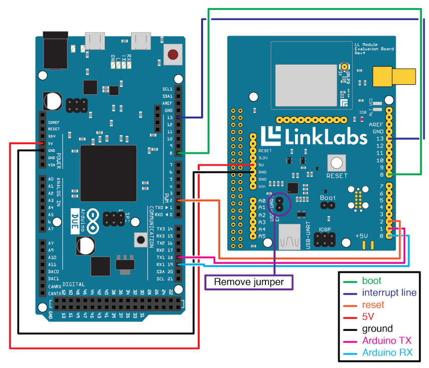
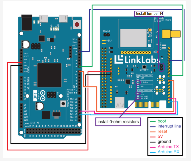
There are slight differences in connecting the various versions of the LL-RLP-20 or LL-RXR-27 evaluation board to the Arduino Due. The following pictures show wire diagrams to highlight the critical connections.
Connecting a Rev. 4 evaluation board
Don't forget to remove the USB-UART jumper, which is normally installed on the Rev. 4 board. Otherwise, you will power the eval board's USB-UART bridge. This causes contention on the serial port used to control the module.
Connecting a Rev. 5 evaluation board (LL3B50)

Connecting a Rev. 6 evaluation board (LL3B60)
With the Rev. 6 eval board, we've tried to make it easier to connect the board to various platforms. You'll need to make sure the 0-ohm resistors circled in purple are installed. Sorry to make you do some soldering!
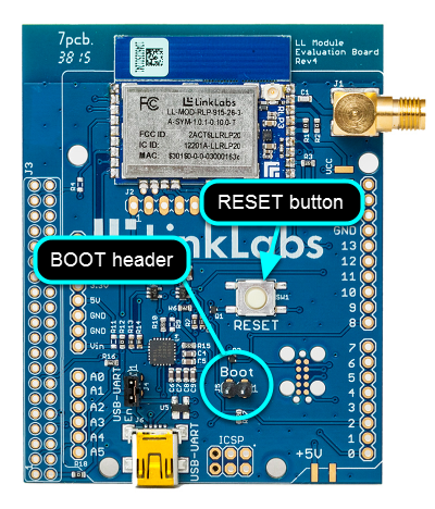
How to place the evaluation board into bootloader mode manually
The evaluation boards' module can be placed in bootloader mode by sending appropriate host interface commands to the module or manually by driving the BOOT pin low while resetting the module. This article describes how to manually place the evaluation board's module in bootloader mode.
Procedure
- Short the evaluation board's BOOT pin by placing a jumper on the BOOT header.
- Press and release the RESET button.
- Remove the jumper from the BOOT pin.
The module is now in bootloader mode.
How to measure the conducted RF power
It is sometimes useful to characterize the RF power generated by the module on an evaluation board. The module typically operates in a frequency-hopping mode, which makes it difficult to measure the power conducted from the module. For this reason, nomac_test exposes the "--tone" function, which causes the module to emit a non-hopping quasi-continuous-wave tone.
To characterize the power conducted by an evaluation board's module, perform the following steps:
- Connect the evaluation board to a PC using a mini-USB cable. Note the COM port enumerated by the evaluation board. If necessary, first install the USB drivers for the evaluation board.
- Connect the evaluation board's SMA connector to a reliable power meter or spectrum analyzer using coaxial cable. Be sure to insert enough attenuation in the path to prevent damage to the instrument.
- Using nomac_test, send the "--mac_set 0" command to set the module to use MAC mode 0 (NoMac mode). Refer to this article to learn how to use nomac_test. Be sure to address the correct COM port.
- Using nomac_test, send the "--antenna_set 1" command to ensure the module conducts the RF tone to the evaluation board's SMA connector.
- Using nomac_test, command the module to transmit a continuous-wave tone using the "--tone" command appended with the desired frequency and power. For example, the following picture shows how to command an evaluation board at COM21 to transmit at a frequency of 915 Mhz and power of 26 dBm.
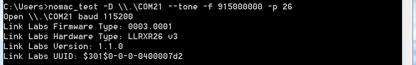
- Record the power measured by the power meter or spectrum analyzer. Be sure to account for any attenuation in the path (connectors, attenuators, cable loss, etc).
- Stop the transmission by sending a different command to the module, such as "--reset_mcu".