Modes of Operation
The LL-RLP-20 or LL-RXR-27 module is designed to be controlled by an external host microcontroller. Link Labs has developed a host interface to operate the module in Symphony Link mode or NoMAC mode. These modes are described below.
Symphony Link Mode
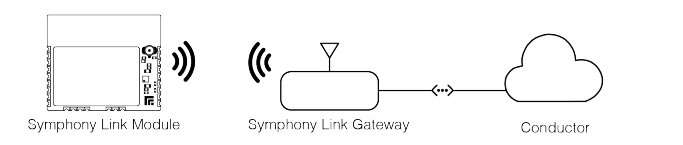
Symphony Link is Link Labs' proprietary over-the-air protocol. It implements a star network based on a slotted Aloha scheme. A simple Symphony Link network is pictured in the figure, above.
In Symphony Link mode, the LL-RLP-20 or LL-RXR-27 module participates as an endpoint with compatible Symphony Link networks. The module automatically connects to an in-range Symphony Link gateway. The gateway relays uplink messages from the module to Conductor, Link Labs' cloud-based data services platform. Likewise, the gateway relays downlink messages sent from Conductor to individually addressed modules.
In Symphony Link mode, the module is controlled using a small set of high-level functions. The details of network operation -- timing, frequency selection, data rate, transmit power, encryption, etc -- are automatically controlled by handshaking between the module and the gateway to optimize network capacity, range and power consumption.
NoMac Mode
NoMAC mode disables the media access control (MAC) firmware and allows the host system to issue low-level commands. NoMAC mode gives the host system direct control of the module's radio parameters, without any automatic network control. NoMAC is useful for network research and development while designing or experimenting with new MAC protocols.
Host Interface Description
The LL-RLP-20 and/or LL-RXR-27 module is designed to be controlled by an external microcontroller (MCU) of the user's choosing. This MCU is referred to as the external host and it communicates with the module using a point-to-point Universal Asynchronous Receive/Transmit (UART) connection. The library of commands available to pass of the UART connection (a C library), as well as the physical connection itself, are referred to as the host interface. This article describes the host interface in detail.
Message Flow
The host interface implements a master/slave protocol where the external host is "master" and the module is "slave." The protocol allows both the master and slave to initiate data exchange, although the mechanism is different for each.
The host interface supports two message types: Command Packets and Response Packets. The master always sends Command Packets, while the slave always sends Response Packets.
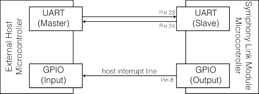
Initiation by the Master
The external host acts as the protocol master and sends one (and only one) UART Command Packet at a time. The master must wait for a Response Packet to be returned from the slave before sending another Command Packet. The slave responds within 300 ms to one Command Packet with one (and only one) Response Packet.
Initiation by the Slave
The module cannot directly initiate a UART transaction. Any unsolicited flow of data from slave to master occurs in the form of a polled interrupt request. The slave initiates a polled interrupt request by asserting the Host Interrupt General Purpose Input/Output (GPIO) line. The host interrupt line is Pin 8 of the module.
If/when the module asserts the host interrupt line, the external host uses appropriate UART Command Packets to query the reason for the interrupt, through a data field called the Host Interface Interrupt Flags (a.k.a. IRQ Flags). Depending on which flags are set, the master proceeds on a flag-specific basis, possibly issuing further commands to continue the data exchange.
The host interrupt line is asserted whenever an interrupt flag is set. It is de-asserted after the master clears all pending interrupt flags.
UART Configuration
|
Nominal Baud Rate |
115200 bps |
|
Data |
8-bit |
|
Parity |
None |
|
Stop Bits |
1 bit |
|
Flow Control |
None |
Message Format
The Command Packets sent to the module and the Response Packets it returns adhere to specific formatting. The following tables describe the format of the Command and Response Packets, respectively. Each type of packet concludes with two checksum bytes, used to verify the integrity of the packet. The compute_checksum function, used to calculate the checksum, is described below. The command bytes themselves -- the "OP codes" -- are listed in the Link Labs Host Interface Library documentation.
|
Command Packet Format |
||
|
Byte Number |
Description |
Comments |
|
0 |
Wakeup preamble 0 |
Always equal to 0xFF |
|
1 |
Wakeup preamble 1 |
Always equal to 0xFF |
|
2 |
Wakeup preamble 2 |
Always equal to 0xFF |
|
3 |
Wakeup preamble 3 |
Always equal to 0xFF |
|
4 |
Start of frame |
Always equal to 0xC4 |
|
5 |
Command Byte |
Specifies which master command is contained in the message |
|
6 |
Message number |
8-bit number incremented by the external host. Expected roll over: 253, 254, 255, 0, 1, 2, … |
|
7 |
Payload length (MSB) |
Most significant byte of the payload length. Note: max payload length is 256 bytes. |
|
8 |
Payload length (LSB) |
Least significant byte of the payload length. |
|
9 |
Payload byte 0 |
|
|
10 |
Payload byte 1 |
|
|
11 |
Payload byte 2 |
|
|
… |
… |
|
|
Payload length + 9 |
Checksum byte (MSB) |
Most significant byte of 16-bit CRC. See the checksum section for further details. |
|
Payload length + 10 |
Checksum byte (LSB) |
Least significant byte of 16-bit CRC. |
|
Response Packet Format |
||
|
Byte Number |
Description |
Comments |
|
0 |
Start of frame |
Always equal 0xC4 |
|
1 |
Command byte |
Specifies the master command to which the module is responding. |
|
2 |
Message number |
Specifies the message number to which the module is responding. |
|
3 |
ACK byte |
00 = ACK: Command Acknowledged 01 = NACK: Command not supported 02 = NACK: Incorrect checksum 03 = NACK: Payload length out of range 04 = NACK: Payload value out of range |
|
4 |
Payload length (MSB) |
Most significant byte representing total number of bytes in payload |
|
5 |
Payload length (LSB) |
Least significant byte representing total number of bytes in payload |
|
6 |
Payload byte 0 |
|
|
7 |
Payload byte 1 |
|
|
8 |
Payload byte 2 |
|
|
… |
… |
|
|
Payload length + 6 |
Checksum byte (MSB) |
Most significant byte of 16-bit checksum. See the Checksum section for further details. |
|
Payload length + 7 |
Checksum byte (LSB) |
Least significant byte of 16-bit checksum. |
compute_checksum
The following function computes the checksum used by the Host Interface to verify the integrity of Command and Response Packets.
/**
* @brief
*   compute_checksum
*
* @param[in] buf
*   byte array to compute checksum on
*
* @param[in] len
*   size of the byte array in bytes
*
* @return
*   The 16-bit checksum
*/
static uint16_t compute_checksum(uint8_t* buf, uint16_t len)
{
    uint16_t i;
    uint16_t crc = 0;
    for(i = 0; i < len; i++)
    {
        crc =(crc>>8)|(crc<<8); crc ^= buf[i];
        crc ^= (crc & 0xff) >> 4;
        crc ^= crc << 12;
        crc ^= (crc & 0xff) << 5;
    }
    return crc;
}
Module Boot Sequence
The module will boot automatically when power is applied and every time the reset line is asserted and then de-asserted. The module notifies the external host that the boot sequence is complete by latching the "reset" IRQ flag and asserting the host interrupt line. The external host must wait for the reset IRQ flag before interacting with the module.
Connection Sequence (Symphony Link mode)
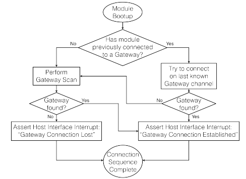
After booting in Symphony Link mode, the module automatically attempts to connect to a Symphony Link gateway. During the connection process, a factory-fresh module will search the entire available spectrum (usually 902 to 928 MHz in the US) for in-range Symphony Link gateways. This can take up to 60 seconds after reset.
If a module connects to a Symphony Link gateway, it stores the network configuration in persistent flash memory. On subsequent reboots, the module will first attempt to reconnect to the same gateway. If the gateway is absent, the module will clear the stored network configuration and search the entire available spectrum for other in-range Symphony Link gateways.
The module notifies the external host that the connection sequence is complete by asserting the host interrupt line. The module will assert either IRQ flag "Gateway Connection Established" or "Gateway Connection Lost". The module will assert the IRQ no later than 60 seconds after reset.
Link Labs Host Interface Library
Link Labs' host interface library (also called ll_ifc) simplifies implementation of the LL-RLP-20 or LL-RXR-27 module. The latest release of the host interface library is available here.
This library is intended to run on the external host, which can be nearly any microcontroller or PC with a UART interface. It is written in ANSI C (C89), which is supported by nearly every C compiler.
Please refer to this website for detailed documentation of the host interface library.
Example Implementation
A good example of implementing the LL-RLP-20 or LL-RXR-27 is the Symphony Link task:
Visit Bitbucket Site
Updating Module Firmware
This article describes several procedures to update firmware to a LL-RLP-20 or LL-RXR-27 module.
If you are trying to update/modify the firmware of a module mounted to an evaluation board, it is easiest to use Prelude's built-in firmware update capability.
At the time of manufacturing, the Renesas microcontroller (Renesas R5F5116ADNE) on the LL-RLP-20/RXR-27 is programmed with the most recent firmware release. During this process, each module is assigned a unique MAC address and encryption keys. A bootloader is also loaded onto each MCU, to facilitate future firmware updates.
The preferred method to re-program a module is to flash firmware to the module via USB from a computer. To implement this method, the module's carrier board must include a USB-to-UART bridge. This allows the PC to interface with the module's UART bus. For example, the LL-RLP-20/RXR-27 evaluation board offered by Link Labs includes a Silicon Labs CP2104 USB-to-UART bridge.
Bootload the module while attached to a computer
This method assumes the module can interface to a computer via a USB-to-UART bridge. For example, the LL-RLP-20/RXR-27 evaluation board includes a Silicon Labs CP2104 USB-to-UART bridge. The firmware update can be achieved using (Method 1) the bootloader_upload_firmware.py script provided by Link Labs or (Method 2) using a terminal like Tera Term.
Method 1: Using Python with bootloader_upload_firmware.py
Download the bootloader_upload_firmware.py Python script, provided by Link Labs. This script uses the standard xmodem and pyserial libraries, so please ensure they are added to your Python installation. The script also uses ll_ifc.py, a Python wrapper for controlling a module from a computer.
Place the desired encrypted firmware file, for example rlp_multi_mac.bin.encrypted, in the appropriate file path. The latest release of rlp_multi_mac.bin.encrypted can be found here.
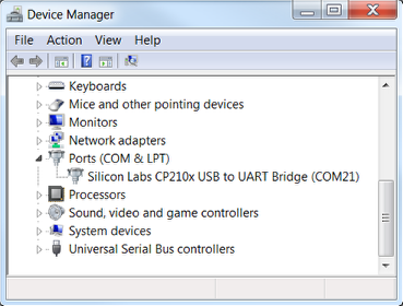
Connect the module to your computer via USB. Note which COM port the USB-to-UART bridge enumerates. For example, in the following picture, the USB-to-UART bridge of a Link Labs evaluation board has enumerated to COM21.
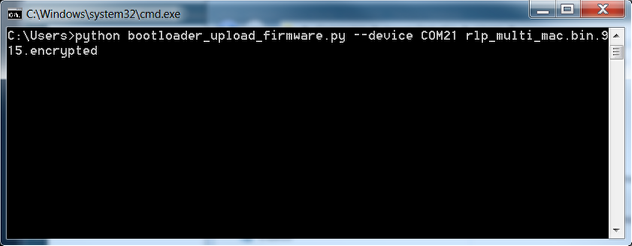
From the command terminal, execute the following command using the appropriate COM port and encrypted binary file path.
python bootloader_upload_firmware.py --device COMxx ~/path/to/encrypted/binaryFor example, the command might look something like this:
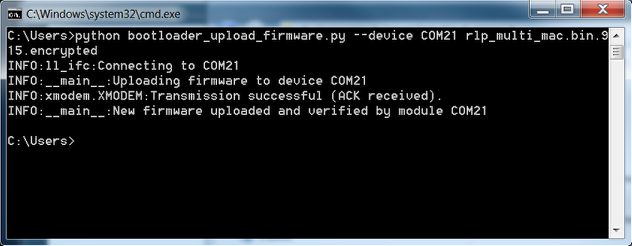
Verify the following successful outcome is achieved:
Method 2: Using Tera Term
The bootloader on the LL-RLP-20/RXR-27 has a human-readable interface. You can view this interface by connecting a terminal to the module's UART.
Connect the module to your computer via USB and open a terminal. In this example, we're using Tera Term.
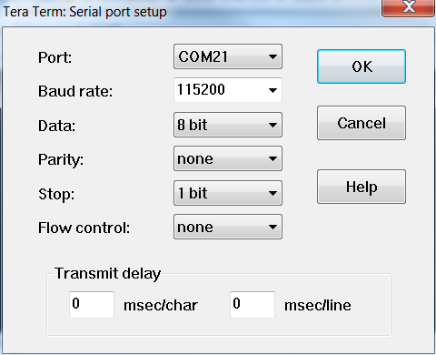
From Tera Term's Setup menu, select Serial Port. Verify the serial port is the correct COM port (in this example, COM21), with the following settings:
Boot the module in bootloader mode. This can be achieved using host interface commands, or by holding the BOOT pin low while rebooting the module. (This article describes how to place an LL-RLP-20/RXR-27 evaluation board in bootloader mode manually.) The Tera Term window will update with the following:
Link Labs Module Bootloader (RX111)
Release v0.10
Firmware is...OK
Enter a command:
 h - help
 u - upload encrypted firmware
 v - verify current firmware
 r - reset
Send the u character by typing 'u' while the Tera Term window is active. This will begin the bootloading process. Then immediately perform the following steps.
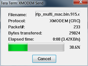
From Tera Term, select File > Transfer > XMODEM > Send. A file tree will appear; navigate to the appropriate encrypted binary file and click Send. (You can download the most recent release here.)Tera Term will send the new firmware to the module.
After successful completion, the Tera Term window will update with:
Verifying...OK
Activating...DONE
Any other response indicates an error in verifying the firmware image. Once the modules sends this response, the firmware has been validated and loaded, and you should send the r character to reboot the module into the new firmware.