LL-LTE-M Modules | LL-LTE-M-VZN-SE Development Kit Quick Start

Create a Conductor Account

User Creation

A new Conductor User can create an account via Conductor's web-based user interface (UI) at conductor.link-labs.com.

While creating a new account, the user will be prompted to enter an email address and Device ID. The Device ID is the MAC Address for Symphony Link devices and the IMEI for LTE Cat-M1 devices. Follow the instructions on the screen and in your email to complete your registration.

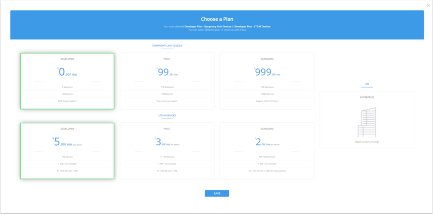
Non-Enterprise Plan users are required to choose a plan and enter billing information to complete the registration process. Enterprise Plan users should contact sales@link-labs.com to complete their registration.
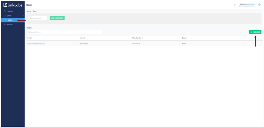
User Management

A User is registered and a plan is selected, the User is assigned to a UserGroup, which associates the user with an account. Authorities are granted to UserGroups, which allow the User to perform actions within the system. Other Users can be added via the User tab on the lrft ribbon and by clicking "Add User" in the upper right hand corner.

See the Access article for more information on the Conductor Security Domain Model.

Read More

LL-RLP-20 or LL-RXR-27 Module | Arduino Library

Arduino Library

Link Labs maintains a sweet Arduino library at our Bitbucket repository. The Arduino library is essentially a C++ wrapper of the host interface C library we provide to control our Symphony Link modules.

Our Bitbucket repo also includes example Arduino sketches, which use the Arduino library and will work out-of-the-box to control an LL-RLP-20 or LL-RXR-27 evaluation board using an Arduino Due. The example sketches are a great way to start rapid application development for Symphony Link. The examples sketches are constantly being updated, so check back frequently.

This chapter explains details about the library, how to install it and use it with Arduino IDE, and what is happening behind the scenes with the Symphony Link module.

Read More

LL-RLP-20 or LL-RXR-27 Module | Evaluation Board

What is the evaluation board?

The evaluation board is a carrier board for the LL-RLP-20 or LL-RXR-27 module. The board includes the following features:

  • A USB-to-UART bridge (Silicon Labs CP2104) to control the module from a PC over USB
  • An SMA connector for convenient routing of the module's RF path
  • A Raspberry Pi B+ header to control the module from using a Raspberry Pi
  • An Arduino header to control the module using an Arduino
Read More

LL-RLP-20 or LL-RXR-27 Module | Over-the-Air File Transfer

Introduction

Following the 1.4.0 release, the Symphony Link protocol supports over-the-air transmission of large files to end-nodes. This capability is useful to update the firmware of the host system, or the Symphony Link module itself.

The Symphony Link File Transfer Protocol (FTP) provides the ability to send files from Conductor to a Symphony Link module. The protocol supports unicast (sending a file to a single end-node) and multicast (sending a file to multiple end-nodes simultaneously).  The FTP is initialized using Conductor's ClientEdge API to send a file to any number of end-nodes.

The protocol sends a file in segments. Each segment is 107 bytes long, with the maximum number of segments in one transfer being 2400. The protocol can therefore transfer a maximum file size of 256 kB.

Symphony Link reserves port 128 exclusively for file transfer traffic.

Read More

LL-RLP-20 or LL-RXR-27 Module | User Guide

Modes of Operation

The LL-RLP-20 or LL-RXR-27 module is designed to be controlled by an external host microcontroller. Link Labs has developed a host interface to operate the module in Symphony Link mode or NoMAC mode. These modes are described below.

Symphony Link Mode

Read More

LL-RLP-20 or LL-RXR-27 Module | Data Sheet

Introduction

What is the LL-RLP-20 or LL-RXR-27 Module?

The LL-RLP-20 or LL-RXR-27 Module is a highly-integrated, low-power, bi-directional radio transceiver module. The modules are optimized for use either in the 915-MHz ISM frequency band or the 868-MHz ETSI frequency band. The modules use a Frequency Modulated Chirp (Semtech's LoRaTM modulation) to maximize range while minimizing power consumption and interference.

The LL-RLP-20 and LL-RXR-27 are essentially identical, with the exception that the LL-RXR-27 includes an onboard power amplifier in the transmit path and a low-noise amplifier in the receive path. The maximum transmit power of the RXR-27 therefore exceeds that of the RLP-20 by approximately 6 dB.

Key Features

LL-RLP-20

  • Receiver sensitivity: -140 dBm
  • Transmit power: 60 mW / 17.5 dBm
  • TX Peak Current: 122 mA
  • RX Peak Current: 10 mA
  • Sleep current: less than 1 uA (regulated/direct), less than 10 uA (unregulated)

LL-RXR-27

  • Receiver sensitivity: -137 dBm
  • Transmit power: 250 mW / 24 dBm
  • Tx Peak Current: 480 mA
  • Rx Peak Current: 40 mA
  • Sleep current: less than 1 uA (regulated/direct), less than 10 uA (unregulated)
Read More

LL-RLP-20 or LL-RXR-27 Module | Module Utilities

Host interface source code - release.tar

The latest release of source code to implement the module's host interface.

release_1_5_0.tar.gz - host interface source code

For a high-level explanation of the host interface, checkout this "Host Interface Description."  For usage and documentation of the command set, checkout the "Link Labs Host Interface Library" documentation.

This release of the host interface source code is compatible with the 1.5.0 release of the LL-RLP-20 and LL-RXR-27 firmware, which includes new features:

Minimum required Gateway Software version is 1.5.2:

  • A Gateway Software update can be performed using the gateway's local web page.
  • For help or questions about upgrading Gateway Software, please contact support@link-labs.com

Deprecated source code to implement the module's host interface.

release_1_3_2.tar.gz - old host interface source code

The 1.3.2 release does not support file transfers and/or use of Repeaters. Link Labs recommends updating to the 1.5.0 release, if possible.

Read More

LL-BST-8 Gateways

Step 1: Turn on the gateway

Connect the antennas.

Connect the 915-MHz antenna to the gateway's UHF antenna jack. Connect the WiFi or cellular antenna to the WiFi or Cell jack (for WiFi / cell enabled models only).

Apply power.

Connect one end of the wall-plug adapter to the gateway's Power port and the other end to an electrical outlet.

Read More